
Thermal Bridge Computation
In this brief tutorial we’ll show you how to computer linear thermal transmittance of a typical thermal bridge: a junction between a wall and a floor. We’ll use Mold Simulator as FEM software for its analysis.
Thermal bridge
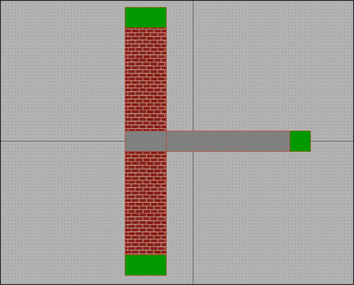
The structure is in contact with external environment (on the left) and internal environment (on the right).
In this case, the thermal bridge is caused by floor; a way to evaluate it is to compute its linear thermal transmittance, ψ (psi) in W/mK.
Linear thermal transmittance
This value represents the difference between the theoretical configuration (just a wall) and the real one (a wall with an intersecting floor).
| Theoretical configuration | Real configuration |
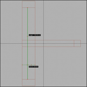 | 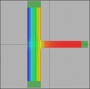 |
| Wall length (l): 1.1 m Wall transmittance (U): 1.0980 W/m²K (computed simply considering wall’s material properties) Thermal conductance (L2D): U x l = 1.2078 W/mK | Wall length (l): 1.1 m Wall transmittance (U): 1.2548 W/m²K (FEM simulation with Mold Simulator) Thermal conductance (L2D): U x l = 1.3803 W/mK (FEM simulation with Mold Simulator) |
Mold Simulator Tutorial 1
You need Mold Simulator Viewer (free) in order to view it.

