Thermal Bridge

Thanks to U-factors feature of Mold Simulator 3, it is possible to compute the contribution of every room to global psi value of a thermal bridge. In this tutorial we’ll refer to file example13.mos contained in Mold Simulator’s documentation folder.
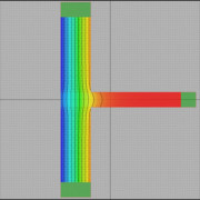
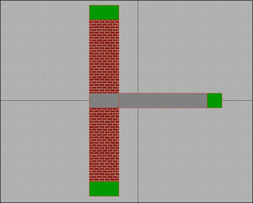
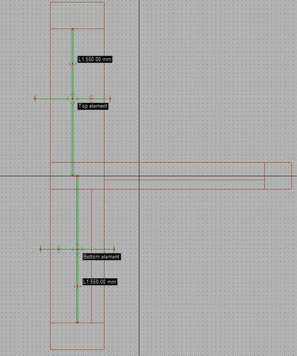
Suppose you’ve a T type of thermal bridge:
Thermal Bridge
It is very important to create two different section elements (“Top element” and “Bottom element”) to get correct results.
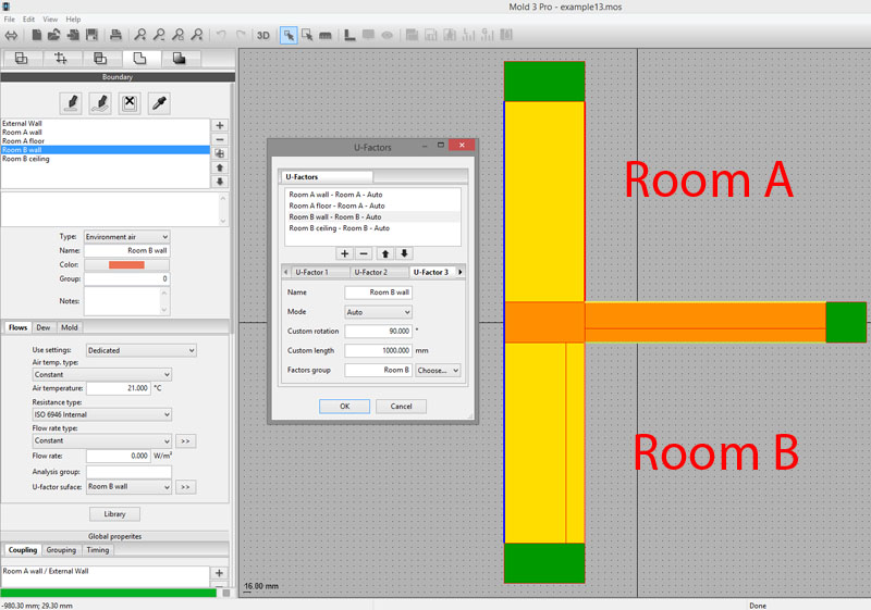
We want to use four different boundary conditions for the internal environments; for this reason you must pay particular attention to boundaries setup.
1- Every internal boundary must have the same temperature;
2- Grouping must be by temperature, but you must disable “Just connected boundaries” option;
3- A separate U-factor surface must be associated to each boundary;
4- U-factors of room A must be grouped under “Room A” U-factors group (same for U-factors of room B).
Thermal Bridge
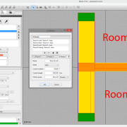
Now you’re ready to get separate linear thermal transmittance contributions of this thermal bridge simply passing to simulation tab.

Thermal Bridge

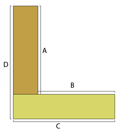
In many thermal bridge computations, you can choose the reference point against which to calculate the linear thermal transmittance (psi). The most common example is the edge of a building:
Thermal Bridge
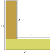
It is possible to calculate psi compared to the internal reference point (lengths A and B) or outside (C and D). Thanks to Mold Simulator 3’s new features, you can do both with a single project following these simple steps:
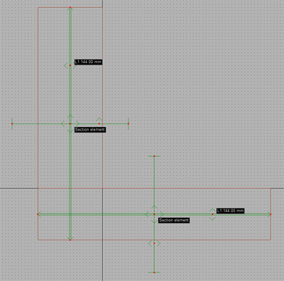
1- plot the section elements to identify lengths C and D of the thermal bridge:

Thermal Bridge
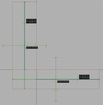
2- change the properties of the newly created items by enabling the “double-length” option. Some new lines will appear for each item;
3- adapt to the new lines in order to identify the lengths A and B:

Thermal Bridge
Turning to “Simulation” tab, you will notice two distinct values of thermal bridge’s linear thermal transmittance (psi): one refers to the internal reference point and the other one to the outside point. For more information, please go to Mold Simulator page.

After two years from the release of Mold Simulator 2, we’re extremely pleased to announce Mold Simulator 3. Aside the huge list of improvements and new features, we’ve added a new version of the software: Mold PSI!, specifically designed for linear thermal transmittance computation. For more information please go to Mold Simulator page.

Thermal Lag - T0

In this article we’ll discuss thermal lag, an important value to take under consideration when analyzing walls and, more in general, building structures. We’ll use our thermal bridge FEM software, Mold Simulator Dynamic, to compute thermal lag in accordance with EN ISO 13786.

In case of simple structures (i.e. a set of homogeneous layers) thermal lag can be analytically evaluated using EN ISO 13786 formulae, but in more general situations a FEM simulation is required.
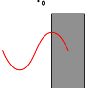
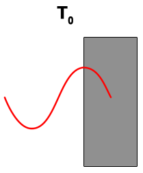
Thermal lag represents a structure’s thermal mass in terms of time; to make it simple, it’s how long it takes to the heat wave to pass through a building structure.


Thermal Lag - T0Thermal Lag - T1
T0: time when temperature is at its maximum on external surface. A sinusoidal heat wave is applied to external surface.T1: time when temperature is at its maximum on internal surface. The heat wave has been delayed and faded.

Thermal lag = T1 – T0 in hours

To have a better understanding of this subject please download this sample for Mold Simulator Dynamic:

You need Mold Simulator Viewer (free) to open it.

Thermal Bridge - Real

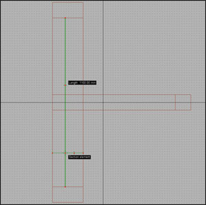
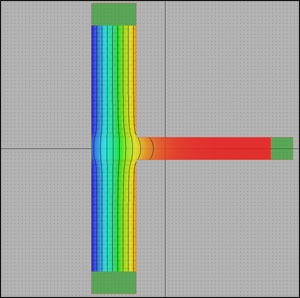
In this brief tutorial we’ll show you how to computer linear thermal transmittance of a typical thermal bridge: a junction between a wall and a floor. We’ll use Mold Simulator as FEM software for its analysis.

Thermal bridge

Thermal Bridge

The structure is in contact with external environment (on the left) and internal environment (on the right).
In this case, the thermal bridge is caused by floor; a way to evaluate it is to compute its linear thermal transmittance, ψ (psi) in W/mK.

Linear thermal transmittance
This value represents the difference between the theoretical configuration (just a wall) and the real one (a wall with an intersecting floor).

Theoretical configurationReal configuration
Thermal Bridge - TheoricalThermal Bridge - Real
Wall length (l): 1.1 m
Wall transmittance (U): 1.0980 W/m²K (computed simply considering wall’s material properties)
Thermal conductance (L2D): U x l = 1.2078 W/mK
Wall length (l): 1.1 m
Wall transmittance (U): 1.2548 W/m²K (FEM simulation with Mold Simulator)
Thermal conductance (L2D): U x l = 1.3803 W/mK (FEM simulation with Mold Simulator)

Thermal bridge ψ = 1.3803 – 1.2078 = 0.1725 W/mK
You can watch an interactive presentation of this tutorial downloading the project:

You need Mold Simulator Viewer (free) in order to view it.