Thermal Bridge

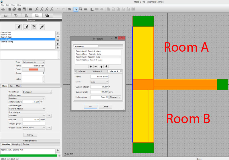
Thanks to U-factors feature of Mold Simulator 3, it is possible to compute the contribution of every room to global psi value of a thermal bridge. In this tutorial we’ll refer to file example13.mos contained in Mold Simulator’s documentation folder.
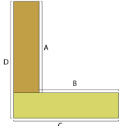
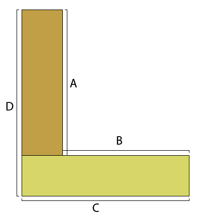
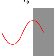
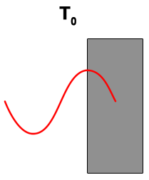
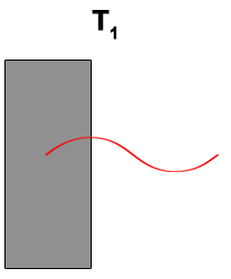
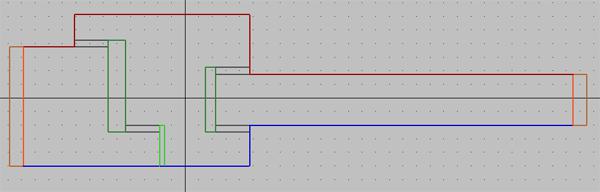
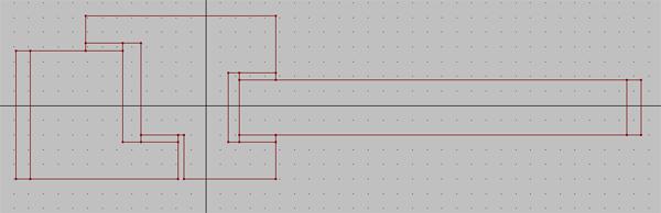
Suppose you’ve a T type of thermal bridge:

Thermal Bridge
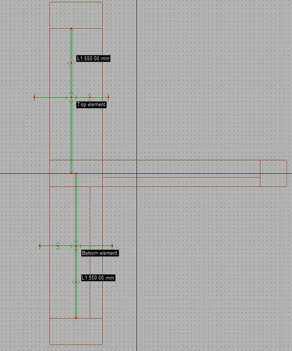
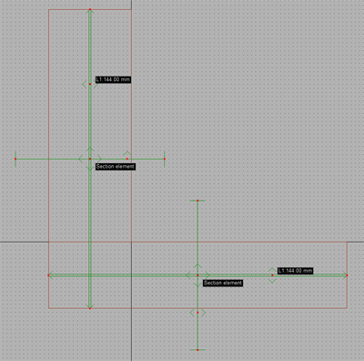
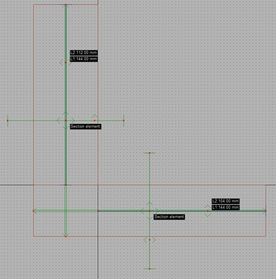
It is very important to create two different section elements (“Top element” and “Bottom element”) to get correct results.
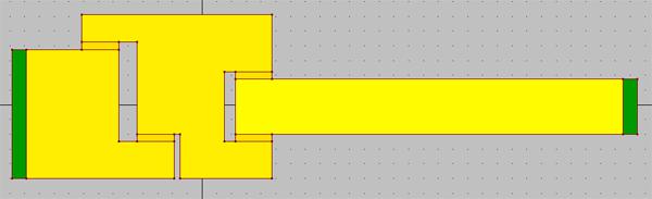
We want to use four different boundary conditions for the internal environments; for this reason you must pay particular attention to boundaries setup.
1- Every internal boundary must have the same temperature;
2- Grouping must be by temperature, but you must disable “Just connected boundaries” option;
3- A separate U-factor surface must be associated to each boundary;
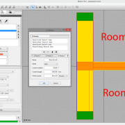
4- U-factors of room A must be grouped under “Room A” U-factors group (same for U-factors of room B).

Thermal Bridge
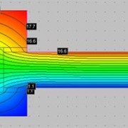
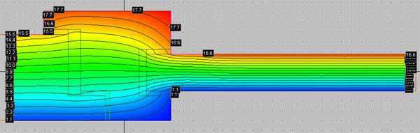
Now you’re ready to get separate linear thermal transmittance contributions of this thermal bridge simply passing to simulation tab.

Thermal Bridge

In many thermal bridge computations, you can choose the reference point against which to calculate the linear thermal transmittance (psi). The most common example is the edge of a building:
Thermal Bridge
It is possible to calculate psi compared to the internal reference point (lengths A and B) or outside (C and D). Thanks to Mold Simulator 3’s new features, you can do both with a single project following these simple steps:
1- plot the section elements to identify lengths C and D of the thermal bridge:

Thermal Bridge
2- change the properties of the newly created items by enabling the “double-length” option. Some new lines will appear for each item;
3- adapt to the new lines in order to identify the lengths A and B:

Thermal Bridge
Turning to “Simulation” tab, you will notice two distinct values of thermal bridge’s linear thermal transmittance (psi): one refers to the internal reference point and the other one to the outside point. For more information, please go to Mold Simulator page.

Thermal Lag - T0

In this article we’ll discuss thermal lag, an important value to take under consideration when analyzing walls and, more in general, building structures. We’ll use our thermal bridge FEM software, Mold Simulator Dynamic, to compute thermal lag in accordance with EN ISO 13786.

In case of simple structures (i.e. a set of homogeneous layers) thermal lag can be analytically evaluated using EN ISO 13786 formulae, but in more general situations a FEM simulation is required.
Thermal lag represents a structure’s thermal mass in terms of time; to make it simple, it’s how long it takes to the heat wave to pass through a building structure.


Thermal Lag - T0Thermal Lag - T1
T0: time when temperature is at its maximum on external surface. A sinusoidal heat wave is applied to external surface.T1: time when temperature is at its maximum on internal surface. The heat wave has been delayed and faded.

Thermal lag = T1 – T0 in hours

To have a better understanding of this subject please download this sample for Mold Simulator Dynamic:

You need Mold Simulator Viewer (free) to open it.

Isotherms

This is the second part of a tutorial about window transmittance computation using Frame Simulator, our FEM simulator available for Windows and Mac OS X. For the first part, please see Window Transmittance – part 1.

In this tutorial we’ll use the following abbreviations:

  • LMB = left mouse button click;
  • MMB = middle mouse button click;
  • RMB = right mouse button click.

Borders definition
Please click “Boundary” tab and select “Internal”; now click on Assign boundary strip button and LMB over one of the lines in contact with intern environment. Similarly, select “External” please click Assign boundary strip button and LMB over one of the lines in contact with extern environment.
In current project, borders should look in this way:

Boundary

Moreover, please make sure to have selected Heat flow direction down flow direction in “Lines” tab.

Simulation
Please click “Simulation” tab and wait that the software performs all the necessary computations. At this point, you can select different types of view: heat flow, temperature, isotherms, etc.
The values required by ISO 10077-2 standard, window transmittance and Lf2D, are shown in “Results” table.

Isotherms

As you have seen, the way to window transmittance following ISO 10077-2 standard is extremely easy with Frame Simulator. We’re planning some more tutorials and articles, so stay tuned!

Wooden Frame

The purpose of this tutorial is to introduce the basic functions of Frame Simulator, through a step by step development of a simple project regarding a wooden frame. The main result we want to get is to compute window transmittance applying ISO 10077-2.
Here you are the project:


Wooden Frame
Typical wooden frame of a window.

  • “ITERNAL” is the frame’s part in contact with intern environment;
  • “EXTERNAL” is the frame’s part in contact with extern environment;
  • “EPDM” has a conducibility of 0.25 W/(mK);
  • “Wood” has a conducibility of 0.13 W/(mK).

Window Transmittance

Insertion of project in Frame Simulator
In this tutorial we’ll use the following abbreviations:

  • LMB = left mouse button click;
  • MMB = middle mouse button click;
  • RMB = right mouse button click.

1 – Lines insertion
Please run the software. The main interface is composed by tabs representing the various phases of project insertion and by a viewport showing frame’s 2D section.
First of all you need to insert the lines composing the frame; this can be done using the tools in the “Lines” tab or you can simply import a DXF file. This should be the result:


Lines
Lines of wooden frame
ISO 10077-2 standard reports a series of rules:

  • Glazing must be replaced with an insulation panel at least 190mm long;
  • The end of the insulation panel must be in contact with an adiabatic surface.

2 – Areas properties insertion
At this point you have to insert the properties of all the areas. Please click on “Areas” tab to enter in areas insertion mode.
Click “Fill area” button and select material type (Standard, Adiabatic, Insulation, Transparent, Glazing gas). In case of standard material, please insert conducibility and emissivity. Usually emissivity is 0.9, except for special materials. LMB in the middle of the areas that you want to create with specific properties.
Areas should look like the following picture:


Areas
Areas of wooden frame
This is the end of the first part of this tutorial on window transmittance; stay connected to see how it ends.